Xidian University Upgrades Existing 2-port VNA to Save Lab Set-up Cost with TMYTEK BBox One
In a 5G mobile terminal, beam scanning capability is a critical factor for mmWave antenna arrays. Here's how TMYTEK enables accurate but simplified antenna testing process.
To overcome the relatively high path loss and to increase the beam coverage, the millimeter-wave (mmWave) antenna array design is a critical circuit design in5G NR mmWave FR2 applications.
Prof. Lu-Yu Zhao’s team at Xidian University has developed a compact 1×4 multi-band and dual-polarization mmWave beam scanning antenna array for 5G mobile terminals. The overall size of the array antenna is small enough to fit into a mobile phone and it fully supports the 5G NR band from n258 to n261.
The antenna element in the array is a critical design that affects the overall antenna array characteristics. It is necessary to validate the array performance through the front-end system by adjusting the phase and gain. Upon completing the antenna array design, Prof. Zhao needed to fully verify the beamforming radiation patterns by setting up a beamforming test environment, which Prof. Zhao aims to build, fast and economically with existing instruments.
Challenge
Beamforming is a necessary technique in mmWave applications. However, antenna array designers must overcome a variety of test limitations before conducting beamforming measurements. To acquire the beamforming radiation patterns, antenna array post-processing is required to simulate the beamforming radiation patterns, or a beamforming front-end circuit to adjust the amplitude and phase.
Before conducting beamforming tests, Professor Zhao faces the following challenges.
Solutions
To achieve the beamforming measurement requirements, and given that Professor Zhao’s antenna design is a compact 1×4 dual-polarized antenna array, TMY Technology Inc. (TMYTEK) suggested three options:
Option 1. Utilize the existing 2-port VNA: It measures the radiation patterns by manually switching each antenna element in a chamber and simulating the beamforming patterns with the post-processing method.
Option 2. An 8-port (or more) VNA: It measures the radiation patterns of each antenna element directly in a chamber, and simulates the beamforming pattern with the post-processing method.
Option 3. Utilize the existing 2-port VNA with TMYTEK’s BBox One: This setup directly measures the radiation patterns in a chamber by adjusting the phase and gain with BBox One.
Of the three options, Option 1 is time-consuming; Option 2 is expensive to set up, requires multiple cables that are not easy to set up in a chamber, and intertwining cables may affect the measurement accuracy or damage the DUT. The above two mentioned options also shared something in common, which is that they both use the post-processing method to simulate the beamforming radiation pattern.
Figure 1 Option 3 Test System

Figure 2 Prototype and measurement setup. (a) Prototype of Professor Zhao’s 4-element antenna array. (b) Measurement setup of S-parameters. (c) Array under test with a BBox One. (d) Measurement setup of radiation patterns.
TMYTEK BBox One helps antenna designers save test time and effort by eliminating the need to develop beamforming algorithms or additional beamforming front-end circuit design. With TMYTEK’s in-house designed GUI, antenna designers can directly control phase, gain and beam direction on one panel, making beam steering and beam management easier than ever before. The combined benefits allow antenna designers to focus on antenna development and efficiently verify antenna performance without worrying about beamforming algorithms.
The TMYTEK BBox One has 16 independent RF channels with individual phase and amplitude control, and therefore Professor Zhao only needed to connect the BBox One to his existing 2-port VNA to test the antenna pattern of his 1×4 dual-polarized antenna at different angles. For Professor Zhao, who needed to measure the beamforming patterns, TMYTEK solution is the easiest, most convenient and cost-effective.
Table 1 Comparison of Various Beamforming Radiation Patterns Testing Options
18 (no of element)15 min(CATR measurement time/round)=120min
*215 min (CATR measurement time/round)
*340 ms (BBox beam switching time/pattern<5ms) + 15 min (CATR measurement time/round) ≒ 15 min
Key Results
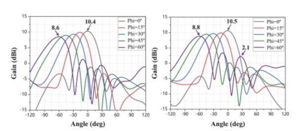
In a 5G mobile terminal, beam scanning capability is a critical factor for mmWave antenna arrays. For comparison, Prof. Zhao measured the beam scanning angle in different directions with his proposed mmWave antenna and TMYTEK BBox One 28GHz, and compared it with the simulated pattern measurement results. As shown in the figure below, Prof. Zhao measured the beam scanning capability of the antenna array at 26.6GHz and scanning angles from 0 to 60 degrees. The difference between the final measurement and the simulation is less than 0.2dB, which means testing using TMYTEK BBox One is just as accurate.
2D beam scanning patterns of the antenna array in the plane of theta = 90°
Figure 3 (Left) Simulated patterns of +45° polarization at 26.6 GHz for the proposed antenna array.
Figure 4 (Right) Simulated patterns of -45° polarization at 26.6 GHz for the proposed antenna array.
Figure 5 (Left) Measured patterns of +45° polarization at 26.6 GHz.
Figure 6 (Right) Measured patterns of -45° polarization at 26.6 GHz.
Figure 7: BBox One GUI developed by TMYTEK, which allows users to intuitively control the amplitude and phase of each channel.
Summary
Prof. Zhao incorporated TMYTEK’s BBox One with his existing 2-port VNA and completed his 1×4 dual-polarization antenna verification experiment within his budget. With 16 independent RF channels, TMYTEK BBox One is applicable to the professor’s various antenna configurations and is used in the OTA chamber to measure the beam patterns to verify the antenna performance. By utilizing TMYTEK’s BBox One, the antenna testing process remains accurate but simplified, and Prof. Zhao does not have to worry about the beamforming algorithm or post-processing.
Reference
Y. He, et al., including Luyu Zhao, “A Compact Dual-Band and Dual-Polarized Millimeter-Wave Beam Scanning Antenna Array for 5G Mobile Terminals,” in IEEE Access, vol. 9, pp. 109042-109052, 2021.


